3D segmentation: application to pore network extraction and to hydrodynamic characterization of soils
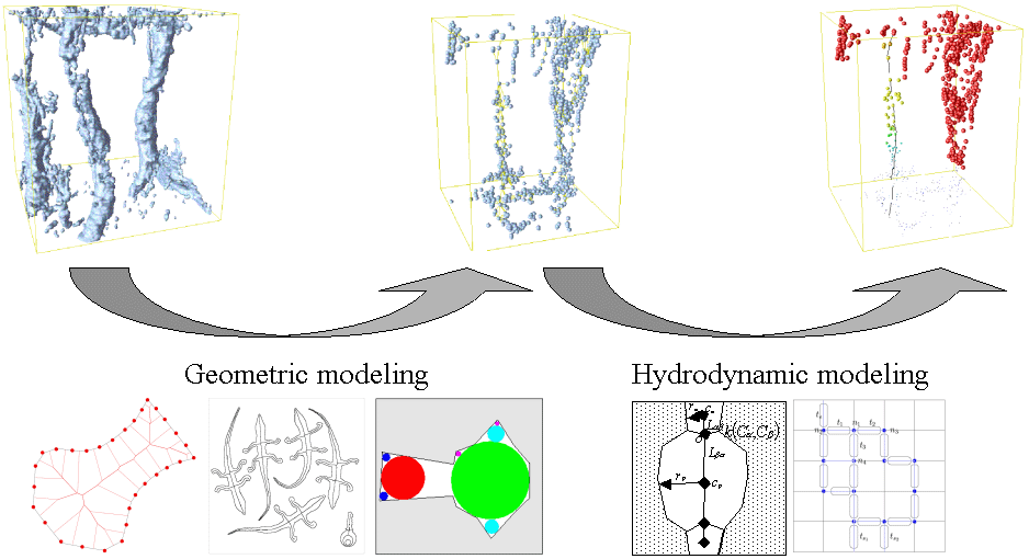
Geometric modeling
The starting point is a binary image. In the case of soil, the foreground can be the pore space and the background the matrix. The geometric description consist in modeling the pore space with a network of pore, elementary objects which constitute the pore space. This geometric modeling is based on a region growing algorithm which needs the use of voronoi diagram and skeleton extraction.
Voronoi diagrams
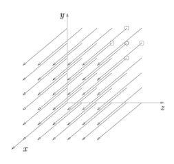
Voronoi diagram computation is based on a discreet segment propagation algorithm in 3D. Seeds are selected on the border of the pore space. Then the image is represented as a set of segment, where each seed own a segment. Segment are stored in a 2D matrix of list of segment to represent the 3D image:
![]()
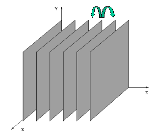
The next step is to propagate the ownership to neighboring lines:
This is done using a two step algorithm which first propagate one line to the other
and then merge propagation with the previous segment list.
This work was done by Guan. My work, done in collaboration with Yu Zeyun consisted in extending this method to the 3D:
 |
 |
Skeleton extraction
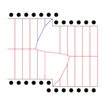
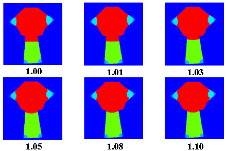
The skeleton extraction is based on a selection of voronoi branches in the voronoi diagram. In the following graph, A and C should be kept but B should be removed.
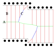
In following cases, the left case should be removed and the right one should be kept.
 |
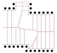 |
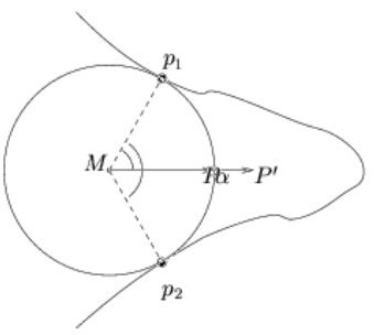
This selection is based on an angle as shown in the next figure.
This algorithm gives good skeleton, centered on the object, and giving distance to the border. However, no proof is given about conservation of the connectivity.
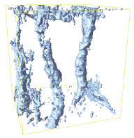
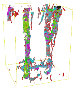
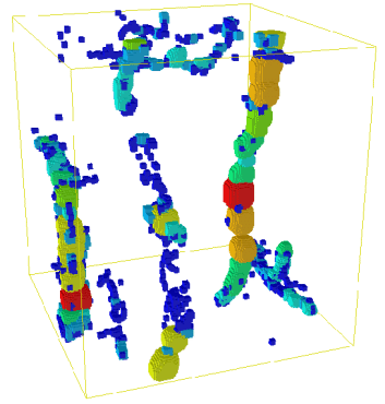
The skeleton (on the right) of a 3D soil image (on the left):
 |
 |
Region growing segmentation
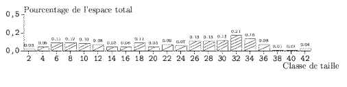
Using the skeleton nd the distance to the border for each point of the skeleton, the object is segmented into object of homogeneous aperture. A first aperture map is computed by drawing circles on the skeleton as shown on the next figure in 3D (and the associated pore size distribution):
 |
 |
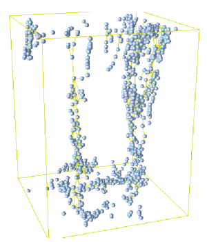
The first step of the region growing algorithm is to place seed in the object. Those seeds are un overlapping maximum balls, centered on the skeleton and touching opposite boundaries:
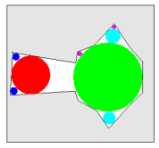
Then make those seeds grown, like if we would inflate balloon into tubes:
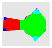
The speed of the growth can depend of the local aperture of the object (using the previously computed Aperture Map):
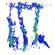
Here is the result on a 3D soil image:
 |
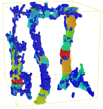 |
| Maximum balls in the pore space | Pore map |
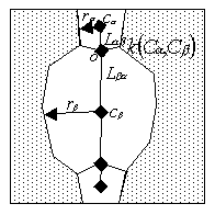
This define a pore map (each separate color define a pore) which is converted into a graph:
Center of pore is either defined using center of gravity or geodesic center.
Link length can be computed using euclidean distance or geodesic distance.
Hydrodynamic modeling
Geometric description of pores
Each pore is described using geometrical parameters such as its local aperture, length, volume, size of interfaces etc.
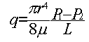
Those parameters are used to compute a local hydraulic permeability using poiseuille law for tubes:
 |
 |
Pore network modeling
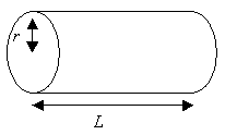
The network previously defined and local permeability are used to run a Pore Network model:
We consider that the algebraic sum of fluxes entering and exiting a node is equal to 0. Thus, we can write for each node an equation. The set of all equation for each node is a system of linear equation where unknowns are local pressure. Then solving the system of equation with a fixed pressure for entrance and exit will give all local pressure. Knowing local pressure allow us to compute the flux entering or exiting the network, and then, using Darcy law, an equivalent hydraulic conductivity for the pore network network.
... To be continued ...